
Modeling a wing mast sail in heliciel
Introducing the mecaflux software suite:
Wings or foils modeling in heliciel
Aerial propeller modeling in heliciel
Boat propeller modeling in heliciel
Ventilation propeller modeling in heliciel
Wind turbine propeller modeling in heliciel
Tidal turbine modeling in heliciel
Kaplan propeller modeling in heliciel
Tutorial building wing or foil (2)
Understand and master the construction of wings or foils part 2:
This second tutorial for deepening the design wing or foil with HELICIEL software, details the options forcing incidence, twisting, or thickness distribution that have been left out of the tutorial "build wing or foil (1l) "
A page about Overview on the wings can be accessed to review the fundamentals to know the design of the wings. Wings, hydrofoils, sails.The calculation of the performance of Heliciel wings uses the theory of Prandtl lifting line. It is quite possible to design your wing without mastering the mathematical foundations of this method (this is the purpose of Héliciel), but the concepts of speed and induced angles introduced in this method are useful to better understand the results given by héliciel. This method is detailed on page: lifting line theory.
We saw in the first tutorial "building wing or foil (1)" how to use Heliciel to study a wing or hydrofoil in the goal of achieving specifications. It may be useful to monitor the incidence and profile shape for greater mastery of performance and resistance.
- Choice of incidence and twist.
It is important to distinguish 2D performance, actual performance (3D) of the wing undergoes speeds induced by the vortices generated by the lift. When Heliciel applies an incidence"geometric" (or pitch) angle, the actual incidence angle received by the profiles is modified by the speed induced by the vortices. The deflection angle produced by the induced velocities is called "downwash". A page about this phenomenon in detail is available: Downwash Théorie- ligne portante-PrandtlVariation of the effective incidence angle generated by the induced speed in the profile of an element.
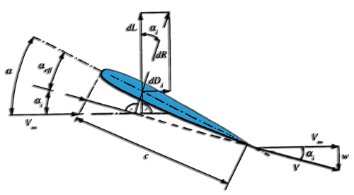
- The velocity V "infinite" is the upstream speed
- Velocity w is the speed induced by the vortices.
- Induced velocity is downward, so it is negative.
- The angle a is the pitch.
- The angle ai is the induced incidence angle .
- Aeff angle is the angle of incidence actually received by the profile.
In this example, we let heliciel apply the angle of incidence corresponding to the best lift / drag ratio (calculated using the 2D performance of the database profiles). Observe the pattern of the profile at the base of the element 3:(right click the 3D prototype scheme.)
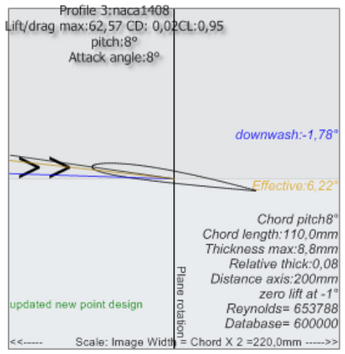
For the wings, the angles of incidence and pitch are identical (here 8 °). Effective angle can be distinguished (6.22°) and downwash angle is -1.78. The downwash angle is the deviation caused by the induced velocities (see: Downwash Lifting line theory-Prandtl), This is the Effective angle that will be taken into account for calculating the performance of our wingWe may change the incidence for the selected element. The "Settings / Control incidence angle" menu, or by selecting the item in the 3D model and right click to open the Management menu item..
Forcing the incidence of a selected item:
by applying a forced 5 ° angle for this profile, we obtain an effective angle of 4.6°
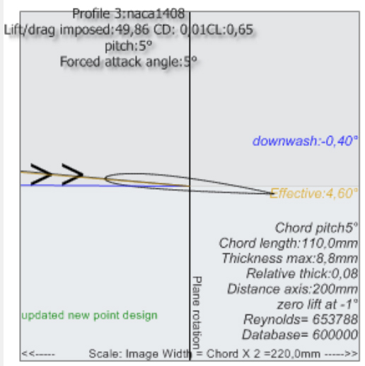
and of course different overall performancewe applied an angle other than the angle of lift / drag maximum, and this affects the 3D performance. This is why Heliciel chooses by default to apply the optimum angle of lift / drag max!
Choice of the distribution of thickness and profile shapes.
- To control the shape, so the thickness of the profile, we can force the profile of the item, choosing from the database profile that we want to apply to the selected item. This option is described on the page "choice profile "
- It is also possible to determine the thickness distribution along our wing by selecting the law of profile thickness. This active in the geometry tab, can fill a required thickness in the blade root and blade tip. A cursor is used to define the thickness distribution between the root and the tip of the wing. This option is detailed in "thickness distribution" page.
 Global site map
 Mecaflux
 Tutorials Mecaflux Pro3D
 Tutorials Heliciel
 Mecaflux Store
 Quotes, Orders, Payment Methods
 project technical studies